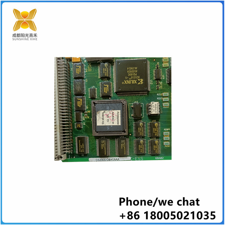
DS200TCQAG1B |5SHY5045L0020| 模拟 I/O 板|
DS200TCQAG1B 是通用电气制造的 RST 模拟 I/O 板,是燃气轮机控制系统中使用的 Mark V 系列的一部分。安装在 I/O 内核 R1、R2 和 R3 上的终端板读取的许多模拟信号都由模拟 IO 板 (TCQA) 进行缩放和调节。LVDT输入、伺服阀输出、热电偶输入、420 mA输入和输出、振动输入、继电器驱动器输出、脉冲输入、电压输入以及发电机和线路信号只是此列表中包含的信号中的一小部分。通过3PL连接器,一些信号被写入STCA板。JE 连接器用于通过 TCQC 板发送和接收发生器和线路信号。TCQA 板可调节 420 mA 输入信号,如压缩机失速检测信号和燃油流量压力信号。
TCQA连接器如下
来自TCPS板的电源使用2PL分配到内核。
3PL - 数据总线是内核中 STCA、TCQA 和 TCQE 板之间的连接。为了传输到COREBUS,有条件的信号在3PL上传输。
磁芯的热电偶输入和冷端补偿分别由 JA 从 TBQA 板连接器 JAR/S/T 传输。
4–20 mA 的输入和输出由 JB 传输到 TBQC 上的 JBR 端子板连接。
JD - 未用于 OR,但将跳闸信号从内核发送到内核中的 TCTG 板。
JE - 将脉冲信号、发生器和线路信号、继电器驱动器输出、伺服阀驱动器输出等传输到 TCQC 板或从 TCQC 板传输。承载电源监视器的输入。
TBQC 端子板连接器 JFR 将 LVDT/LVDR 位置输入发送到 JF。
JG 承载 +/- 10 V 直流输入以及来自 TBQB 端子板连接 JGR 的振动输入。
TCQA软硬件配置
硬件:使用硬件跳线 J1 和 J2 选择 mA 输出电路。mA 输出电流范围(最大值为 20 mA)或最大值为 200 mA,使用 J5 和 J6 进行配置。对于卡测试,J7 中使用 RS232 端口。J8 打开振荡器。有关此板的硬件跳线设置的详细信息,请参阅附录 A 和操作界面的硬件跳线面板。
软件:热电偶、脉冲速率、振动、LVDT 位置以及 420 mA 输入和输出 I/O 配置常数在操作界面上的 I/O 配置编辑器中输入,如下所述。
脉率输入电路
用于调整和调节脉冲速率输入以通过 JE 连接器从 TCQC 板读取的电路位于 TCQA 板上。这些信号从TTL(晶体管到晶体管逻辑)和磁拾音输入输入到QTBA和/或PTBA端子板中。高压轴速度输入被发送到“R1”磁芯。还有其他信号可以与R2和R3上的脉搏率输入电路一起使用。
TCQA 4-20 mA 输入电路
420 mA和01 mA输入信号的电路由TCQA板提供。通过 JB 连接器,从 TBQC 端子板读取信号。负载电阻两端的压降是由传感器的电流降引起的,由 TCQA 板测量,并通过 3PL 连接器写入 I/O 引擎。输入信号的电流范围使用TBQC端子板上的硬件跳线进行选择。
TCQA 4-20 mA 输出电路
通过JB连接器将420 mA输出驱动到TBQC端子板的电路由TCQA板提供。通常,这些信号用于为控制设备供电。

The DS200TCQAG1B is an RST analog I/O board manufactured by General Electric and is part of the Mark V series used in gas turbine control systems. Many of the analog signals read by the end boards installed on the I/O cores R1, R2, and R3 are scaled and adjusted by the Analog IO Board (TCQA). LVDT inputs, servo valve outputs, thermocouple inputs, 420 mA inputs and outputs, vibration inputs, relay driver outputs, pulse inputs, voltage inputs, and generator and line signals are just a few of the signals included in this list. Through the 3PL connector, some signals are written to the STCA board. JE connectors are used to send and receive generator and line signals via the TCQC board. The TCQA board adjusts 420 mA input signals, such as compressor stall detection signals and fuel flow pressure signals.
The TCQA connectors are as follows
Power from the TCPS board is allocated to the kernel using 2PL.
The 3PL-data bus is the connection between the STCA, TCQA, and TCQE boards in the kernel. For transmission to COREBUS, conditional signals are transmitted on 3PL.
The thermocouple input and cold end compensation of the core are transmitted by JA from the TBQA board connector JAR/S/T, respectively.
The 4-20 mA input and output are connected by the JBR terminal board transmitted by the JB to the TBQC.
JD - is not used for OR, but sends trip signals from the kernel to the TCTG board in the kernel.
JE - Transmits pulse signals, generator and line signals, relay driver outputs, servo valve driver outputs, etc. to or from the TCQC board. Carries the input of the power monitor.
The TBQC terminal board connector JFR sends LVDT/LVDR position input to the JF.
The JG carries the +/ -10 V DC input and the vibration input from the TBQB terminal board connected to the JGR.
TCQA hardware and software configuration
Hardware: Select the mA output circuit using hardware jumpers J1 and J2. mA Output current range (maximum 20 mA) or maximum 200 mA, configured using J5 and J6. For card testing, the RS232 port is used in J7. J8 Turn on the oscillator. For more information about the hardware jumper Settings for this board, see Appendix A and the Hardware Jumper panel of the operating interface.
Software: Thermocouple, pulse rate, vibration, LVDT position, and 420 mA input and output I/O configuration constants are entered in the I/O configuration editor on the operating interface, as described below.
Pulse rate input circuit
The circuit used to adjust and adjust the pulse rate input to be read from the TCQC board via the JE connector is located on the TCQA board. These signals are fed from TTL (transistor to transistor logic) and magnetic pickup inputs into the QTBA and/or PTBA terminal boards. The high pressure shaft speed input is sent to the "R1" core. There are other signals that can be used with the pulse rate input circuitry on R2 and R3.
TCQA 4-20 mA input circuit
The circuits for the 420 mA and 01 mA input signals are provided by the TCQA board. The signal is read from the TBQC terminal board via the JB connector. The voltage drop at both ends of the load resistance is caused by the current drop of the sensor, measured by the TCQA board and written to the I/O engine via the 3PL connector. The current range of the input signal is selected using the hardware jumper on the TBQC terminal board.
TCQA 4-20 mA output circuit
The circuit to drive the 420 mA output to the TBQC terminal board via the JB connector is provided by the TCQA board. Typically, these signals are used to power control devices.


